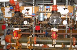
Fire & Life Safety: Sprinkler Monitoring, Level II
I covered electronic supervision and monitoring of common sprinkler systems in my November column. Now, let’s move to the less common fire suppression systems — use this column as a companion to the earlier one, which outlines how to generate RMR by servicing these signals and systems.
Many fire suppression companies stick to what they know best — running pipe. This usually leaves the wiring and electrical components to be provided by you, the fire alarm contractor. Once you obtain the contact information of the suppression system provider from the property owner, architect or project manager, contact them to coordinate the connection of their suppression system to the building’s fire alarm system. Be ready to identify the name of the building, city, and street address; as well as identifying yourself and your company and providing contact information. You can ask to meet them at the site to verify the locations of all of their initiating devices.
There will always be two kinds of initiating devices: Alarm and Supervisory. If a releasing panel is installed (see system descriptions below), then you are required to connect to the three relay contacts provided on the releasing panel so the Alarm, Supervisory, and Trouble signals on the releasing panel will be indicated on the building’s fire alarm system. This is not optional. You must provide three different IDCs from your panel or three addressable input modules on your panel’s SLC to duplicate (monitor) all three releasing panel signals via the building’s fire alarm system. If the suppression contractor is not providing a releasing or control panel with their suppression system, then you will not have to connect any Trouble contacts.
Use the following descriptions as an introduction to help you identify various open-contact switches the suppression system contractor may have installed for you so that you will be able to initiate the required Alarm and Supervisory signals.
Systems to Know and Understand
Dry-pipe suppression systems are found in buildings and spaces where the sprinkler pipes may be exposed to low temperatures and freezing may occur. Dry-pipe systems are more common in northern parts of the country and in refrigerated storage areas. In addition to water shut-off valves, these dry-pipe systems will have a few more supervisory switches to connect to your FACP than a basic wet-pipe system.
Dry-pipe systems will never use a paddle-type waterflow switch that clamps to the riser using a large U-bolt. Instead, they use a port in the large cast iron valve on the main riser that is not exposed to water or air pressure until the valve’s “clapper” uncovers this port — when the loss of air in the dry pipes allows the city water to burst into the valve and shoot to and out of the sprinkler head that opened due to high heat. When the valve’s clapper opens, it also exposes a port leading to the pressure-type waterflow alarm switch (usually at the end of a short pipe) to this same rush of water.
An air pressure supervisory switch is used to supervise the pressurized air in the dry-pipes to warn when it is too high or low by 10 psi. It is usually installed near a large brass air pressure gauge that indicates the actual pressure in the pipes. On the other hand, the alarm (pressure-type) switch will not have an air pressure gauge on the pipe on which it is installed.
You will soon recognize that the waterflow alarm and air supervisory switches are very similar in appearance! When deciding if a pressure switch is an alarm switch or supervisory switch, I do not recommend using the manufacturer’s part number and description shown on the switch alone to make this determination — I have found instances where the suppression contractor had mixed up these two types of pressure switches. You must learn to recognize where they are physically located (to initiate an alarm or supervisory signal) and then read the printing on the switch to verify it is being used correctly. Should they need to be changed, contact the company that installed them originally so they can make the change. You must NEVER accidently let the pressurized air escape when testing the air pressure Supervisory switch!
Allowing the water to flow into frozen pipes means that the pipes will then have to be thawed and drained, and the dry-pipe valve will need to be disassembled and the clapper re-set by the sprinkler contractor. This goof on your part may require the temporary removal of goods from a cold storage area, for example, resulting in spoilage, loss of revenue and the additional cost of providing temporary storage at another location. Not to mention the loss of confidence in your expertise by the property owner who most likely will not renew your fire alarm company’s test and inspection contract.
Pre-action fire sprinkler systems use the same basic design as dry-pipe systems, in that water is held back from entering the sprinkler pipes and heads. In this case, however, the water is held back by an electrically-operated valve, known as the “pre-action valve.”
A FACP specifically listed for releasing will be activated only by devices connected to this panel, which is usually installed by the suppression system contractor. On an alarm input, it will signal the releasing panel to open the electrically-operated valve holding the water/foam back from entering the pipes over rooms and spaces containing high-value equipment and property. Water is now in the overhead pipes and is only being held back by the closed sprinkler heads. This sequence of operation is used as a stop-gap precaution against leaks in the sprinkler pipes, causing water damage in critical areas of the building. Such areas typically contain computers, electronic equipment, laboratories, historic archives, paper records and irreplaceable objects.
When the releasing panel allows water to enter the pipes, a local pre-alarm warning will signal the occupants to take action such as leaving the room or space, protecting its contents, extinguishing the fire by hand, cutting power to critical systems, or backing up data before the heat builds up high enough to open sprinkler heads. Since a “Dedicated Function” releasing panel is always installed with pre-action systems, you must simply connect the three relay contacts provided on the releasing panel, so that all Alarm, Supervisory and Trouble signals initiated by the releasing panel will also be indicated on the building’s fire alarm system.
You will only provide the monitoring of the releasing panel, since all initiating devices used for releasing purposes must be connected to it. You will install alarm notification appliances in the area served by the releasing panel just as you have for the rest of the building.
A Deluge system is similar to a pre-action system except the sprinkler heads are already open, which allows all sprinkler heads to operate without delay upon any alarm activation. These systems are used to suppress fires of highly flammable materials. “Blast walls” may be associated with areas served by deluge systems. Again, simply connect all Alarm, Supervisory and Trouble signal contacts found on the releasing panel so these are duplicated on the building’s fire alarm system.
Generators and fire pumps will also have their own control panel or “controllers.” Panels associated with this type of equipment will usually have a common set of “Trouble” contacts. You will wire to these dry contacts to initiate a supervisory signal, which you will annunciate as “Fire Pump Trouble” on your building’s alarm system. Some fire pump controllers may provide contacts for several specific trouble conditions such as “phase reversal”, “fail to start”, etc. Check to see if the job specs require specific fire pump trouble conditions to be individually annunciated. If not, NFPA 72 allows you to annunciate all fire pump trouble conditions on the building’s FACP as a single common supervisory signal.
Responding personnel will go to the pump room (or a remote fire pump annunciator supplied by the pump’s manufacturer) to view the pump’s controller display to determine the specific pump condition that is causing the supervisory signal annunciating on the building’s main fire alarm panel. Don’t get confused when reading specifications, installation manuals, codes and standards that require a fire “pump trouble” or “duct detector trouble signal” to cause a supervisory signal on the building’s fire alarm panel, but defined/annunciated as a “trouble condition” in the equipment you are supervising.
Greg Kessinger is SD&I’s fire alarm and codes expert and a regular contributor. Email him your fire & life safety questions at [email protected].


